Velocity up to 3 ms on the gross area of racks may be permitted where serious clogging of trash racks is not expected for high-pressure. 2 September 1997 NORSOK standard Page 6 of 17 455 Utility headers Utility headers for water steam air etc.

Steel Frame Pipe Rack Tutorials Computers And Structures Inc Technical Knowledge Base
Rack loading for member sizing after 30 model review.
. Conservative loads are to be provided. Minimum 3 Meters clearance provided below Units Pipe racks not crossing any roads. Calculating loads on the pipe racksYour trainer proceeds step by step through the process of modelling columns beams stringers bracingapplying dead loads product loads thermal loads wind loadsNext he proceeds further on how to assign the properties to the structural steel members assigning the releases.
Hello All As a new member of piping design team I have to compute and deliver loads imposed by piping on a T-shaped pipe rack of petrochemical plant. Up to 10 cash back You will start with the absolute basics ie. 62 For high pressure intakes the overall economy will determine the velocity to be used in racks.
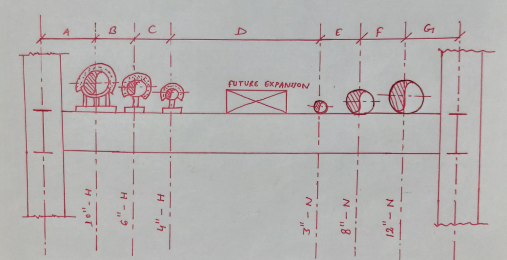
Any pipe rack design should provide provision for future growth to the extent of 2530 on the rack clear width. 19 rows Some of these points are covered in following pipe rack design checklist. The width of the rack shall be 6m 8m or 10m for single bay and 12m 16m or 20m for double bay having 4 tiers maximum.
25 Extra space provided for future expansion. However pump sizes and installation of pumps below pipe rack may need more increased to 8m. This paper summarizes the building code and industry practice design criteria design loads and other design consideration for pipe racks.
However it can be increased to 8m depending on the size of the pumps to be housed below the pipe rack. When flanges or flanged valves are required on two adjacent lines the flanges are to be staggered. A 64 eccentric reducer FOB is welded to the west side of the tee.
6 rows Pipe to pipe distance Larger flange radius larger pipe insulation thickness 25 mm Gap. Loads to be provided based on actual analysis. Live Load shall be applied on platform in the top level of rack as servicing cooling tower access.
46 Valves 461 Accessibility and installation. Rack loading for final member checking after 60 model. Where consideration of uplift or system stability due to wind or seismic occurrences is required use 60 of the.
Shall be arranged on the top of multi-tiered pipe racks. Non-building structures pipe racks support design. Pipe Rack Load Calculation Pipe Rack Load Calculation Vikoll Mechanical OP 11 Feb 08 1402.
Distance along X to design for shear Dx. Students will be able to model analyze and design the Pipe Rack in STAAD Pro They will be able to understand how the steel structures are designed. In general spacing between pipe rack portals or bays shall be taken as 6m.
From above calculations 075 X Vc. The width of the rack shall be 6 m 8 m or 10 m for single bay and 12 m 16 m or 20 m for double bay having 4 tiers maximum. OR1ONiAL This calculation verifies pipe support.
At a centerline elevation of 110-3 5 16 an elbow turns south travels 3-2 turns up 2-0 into the Main pipe rack and tees again branching in the east and west directions. Pipe Rack Drawing for Oil Field. Most of the data has started arriving.
Critical load case for Vux is. This checklist can be used at design stage as well as during 3D Model Review. The structural adequacy of the subject Legibil 8Wc ity evaluated and peydfor aUe 9305280306 930522 PDR ADOCK 05000390 Signature p A PDR C Microfilm and store calculations in RIMS Service Center.
In this case the E-W pipe rack height will be 12 from grade and the N-S pipe rack height will be 15 from grade. Design calculation report - Pipe rack - and foundation. Several industry references exist to help the designer apply the intent of the code and follow expected engineering practices.
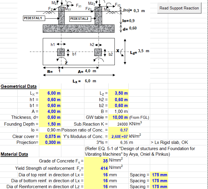
All the information provided by the sturcutral engineer regarding the pipe rack foundations are shown in the following figure and design data. Primary loads Eo and Ee are developed and used in separate load combinations to envelope the seismic design of the pipe rack. A transposition drawing takes the.
The spacing between pipe rack portals shall be taken as 6m in general. Storage racks found in warehouses are not pipe racks even if they store lengths of pipe. There are several ways to determine the width of a pipe rack.
Wind seismic snow etc loads are not a. Piping design layout and stress analysis L-002 Rev. P W - s x p x d s Spacing of pipe rack bent p pipe weight considered kPa d pipe diameter W pipe concentrated load.
They will be able to calculate Dead Load Product Loads Thermal Loads and Wind Loads as per ASCE 07-10 Valuable Resources that they can use in their Regular Design Calculations. This is usually done during the plot plan development by creating a piping transposition drawing from PIDs and a preliminary equipment layout. Check that 075 X Vc Vux where Vux is the shear force for the critical load cases at a distance deff from the face of the column caused by bending about the X axis.
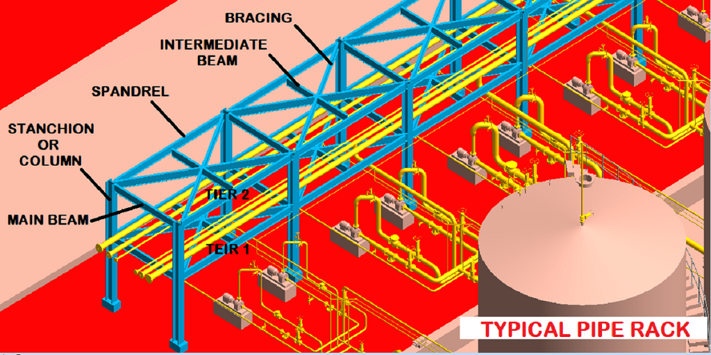
Pipe racks are structures in petrochemical chemical and power plants that are designed to support pipes power cables and instrument cable traysThe design requirements found in the US building codes are not clear on how they have to be applied to pipe racksThis course summarizes the US design code requirements and industry practice design criteria. Pipe Rack Design Philosophy. Document design calculations for pipe support referenced in calculations title.
These loads will be used by structural for pipe rack design. Piping design places the lines over the rack based on preliminary PID. ASCE Guidelines for Seismic Evaluation and Design of Petrochemical Facilities 1997 also provides further guidance and information on seismic design of pipe racks.
Therefore in order to provide for a nominal unbalance of friction forces acting on a pipe support a resultant longitudinal friction force equal to 75 of the total pipe weight or 30 of any one or more lines known to act simultaneously in the same direction whichever is larger is assumed for pipe rack design. This case study focuses on the design of pipe rack foundations using the engineering software program spMats. Live Load in operating or maintenance platform are 250 kNm2 Live Load 25 x 3 75 kNm --- span 3 m Page 7 of 15 f CALCULATION OF PIPE RACK STRUCTURE Doc.
Design of Structural Steel Pipe Rackspdf. Of rack bars and where mechanical cleaning of racks is provided a velocity up to 15 ms should be permitted. Width of Pipe rack.
Rack loads are provided mostly based on assumptionexperience.

Pipe Racks An Overview Sciencedirect Topics

Design Of Pipe Rack Layout Considerations
Pipe Rack Design And Calculations Make Piping Easy
Pipe Rack Design And Calculations Make Piping Easy
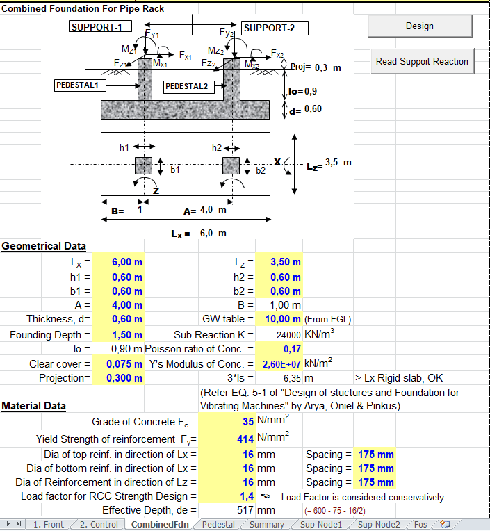
Combined Foundation For Pipe Rack Spreadsheet
Pipe Rack And Pipe Track Design And Engineering
Combined Foundation For Pipe Rack Spreadsheet

Steel Frame Pipe Rack Tutorials Computers And Structures Inc Technical Knowledge Base
0 comments
Post a Comment